Parkside Memories, 1959 to 1989
De-Watering the Shafts
On completion of all the insets, the next job was to de-water the shafts. The strata through which the shafts had been sunk contained a lot of water bearing sandstone. There was a joint every 15ft in the concrete lining of the shaft and most of these leaked water. When the last inset was finished, the water level was up to No2 inset and that's a lot of water! At least 1000ft deep.
To do the de-watering, a couple of hoppits were modified. A round hole was burnt out of the base, about 2ft in diameter and around this welded a ring of steel rods approximately 3ft long to form a cage. Inside this cage was placed a solid rubber ball, slightly bigger than the aperture in the base, a plate being welded on top of the cage to stop the ball from coming out. The sinking stage was taken to a position just above the water level in the shaft, and baling began. The hoppit plunged into the water, displaced the ball and allowed the water into the hoppit. When it was full, the ball sank down to plug the hole and the full hoppit was wound to the surface, and as it landed there, the lazy chain was used to tip it just as it did when mucking operations were taking place. A duct constructed from ventilation tubing carried the water away from the shaft and into the surface drains. In less than a week, both shafts had been emptied. I remember standing in the water duct as the hoppit was tipped and feeling the heat from the water as it ran away.
One story worth recalling about this episode concerns David Bentham. At the bottom of the shaft, after the water had been removed, there was a residue of evil smelling mud about 6 ft in depth. The sinkers had placed planks of wood on the surface of it to walk on and this could be done, if care was taken, but David, being a bit impetuous, jumped out of the hoppit and sank up to his neck in the smelly slime. When he reached the surface, he had to be hosed down to get rid of it! David was later put in charge of the grouting of the matching joints in the shafts, the sinking stage still being used for this. There was a joint every 15ft, and this was where the curb had been placed to hold the concrete shutter as the shaft was lined during sinking operations. Water ran into the shaft from the sandstone strata and gas escaped from the coal measures, and these leaks had to be plugged before any equipping could take place. To do this, a hydraulic pump was installed on the top deck of the sinking platform, and liquid cement pumped into holes drilled in the shaft wall at the matching point by use of a "bougie" pipe. Some of the holes took up to a ton of cement, but it did the job, and soon the shafts were a lot drier.
At the bottom of the shafts was a small connecting tunnel. No2 shaft was 10ft deeper than No1, and this formed a sump hole to collect any water that came down the shafts. When the mud and slime had been removed, a three-cylinder ram pump was installed to pump the water to No3 inset, from where it was pumped to No2 inset and finally to No1 inset, whence it was pumped to the surface. It had to be done this way, as the head of water was too much to pump it directly to the surface. The ram pump was shattered a couple of times, and this is how it occurred. When we first started to operate it we didn't realize that a ram pump was different from a centrifugal pump. To operate the latter you start with the outlet valve closed, but definitely not with a ram pump.
I went down to the sump when the ram pump had been installed and was shown how to start it. The first time on my own and it happened. Forgot the valve, switched on and a "crunching" sound were heard. I went up to see the engineer in charge, a man by the name of David Holmes. He was a really nice chap. I was lying through my teeth. "Yes Mr. Holmes, I opened the valve." He said, "Are you definite about that? " "I'm positive" "Well," He said "It's a mystery to me," I never told him any different, but later on, someone else did the very same thing, and they also swore that the valve was open. They finally put a by-pass valve into the pipe range to avoid a recurrence.
Until the shafts had been completed, we three from Stones had done no weekend work, but this was soon to change when the pumps were installed. We had to take our turn on the rota for pumping and what a job it was!
A typical night's work was as follows: - Get changed into waterproofs and put on a shaft hat. Pick up a cap lamp and proceed to the pit bank to take up a position in the hoppit, armed with a hooked piece of steel rod known as a "boat hook." The banksman then signalled the winder to lift the hoppit, opened the shaft door and sent it to No1 inset. Arriving here, the boat hook was used to catch hold of the end of the bridge that was in a vertical position in the inset, held in place by a counter weight. The bridge was pulled down and hooked on to the side of the hoppit rim. You walked across the gaping chasm of the shaft on a piece of plank about 1ft wide, with handrails on either side. Once inside the inset, the pump was checked, the oilers filled and it was back to the hoppit.
To signal the hoppit away you had to snare the line hanging down the shaft by using the boat hook. The signals were as follows: - 3 for manriding, followed by 8 for No2 inset, 2x3 to signal no onsetter, then a further 2 to lower away. All these signals executed with your arms at full stretch and water running down your arms and into your jacket. Sometimes, when the winder didn't get the entire signal, he wouldn't move, and the whole process would have to be repeated. This procedure was repeated at each inset with the station signal being increased by 1 each time. 7 to No1, 8 to No2, 9 to No3 and 10 to the sump. When you had been to every inset you needed a break. I wondered if I had made the right decision to come to Parkside!
There was one job that we three from Stones were given that was really interesting, Joe Corday came up to us one day and said "Neh lads, ah've getten a good job fer yo, yur gooin t'build aw t'bins in t'new stores". Thus informed we went into the new stores building that had recently been completed, and saw there a pile of what looked like Meccano. Angle iron, shelves, brackets, nuts and bolts. He gave us a plan to work to and we set about the job. I reckon that it took about a week to assemble it all, fitting all the nuts and bolts. When we finished I must say, it looked quite good. The only thing was, that when the store men came to use it, a lot was dismantled and re-assembled to suit them.
At that time the fitting shop and blacksmiths' shop were being fitted out, and I recall that the electricians who were wiring them were using Hilti guns to fix the cable trays to the girders. I'd never seen one before and the racket was unnerving. They used 0.32mm cartridges and the gun could shoot a nail straight through an RSJ.
There was a small canteen situated in the main block and this was used mainly for the office staff, but the lady in charge, by the name of Annie, used to warm a tin of condensed soup for Ronnie Adamson and me, which we split between us. We paid for this alternatively each day! Around this time, work was going on to build the second phase which included deputies baths, main baths, pay hall and canteen which Fairclough had the contract for. There was a gang that came to fit the tower lifts, and they came from Staffordshire and the firm that they worked for was Etchells, Condon and Mitchell, or ECM.
Until the lifts were installed, the only way up the towers was by way of the stairs. This was a bit hairy as they had no handrail and, as the lift shaft was wide open, a good head for heights was required if you went up them. The towers were being finished off and the men fixing the windows had to hang from the top on bo'sun's chairs to fit the concrete lintels and cills. It wasn't a job that I fancied doing. In fact, later on, 2 men were killed when they fell from a chair whilst painting an overhead gantry.
Fitting the Permanent Winders
In the spring of 1960, work started on the installation of the permanent winding systems, made in Barrow-in-Furness factory of Vickers Armstrong Ltd and I was seconded to assist the team of fitters who were in charge of the NCB side of operations. These were Harry Green, fitter, Rueben Pownall, apprentice, Harry Wain, fitters mate and later on, Roy Davies and Joe Livesey, fitters.
The top floor of No 1 tower was bare concrete, with no windows, just holes in the walls with boards across to stop anyone from falling out. Over in one corner was a gaping hole through which the machinery was to be winched from ground level, and it was freezing cold up there. Around the hole in the floor was a piece of scaffolding tube as a fence, and one day, I could see a screwdriver lying on the floor at the side of the hole, just out of reach. I stretched out my arm, but I couldn't reach it unless I leaned out over the gap. I looked down and "chickened out". No way would I have reached for the screwdriver! Just then, one of the scaffolders came by. He was a big black lad named Ronnie, and I showed him the screwdriver. He reached across the hole without a second thought, grabbed it, and pocketed it. I would have liked it myself, but I thought, "You can have it"!!
The surveyors came up and gave us a datum line to work from. This consisted of a piano wire, stretched between two stands bolted to the floor and from this all subsequent measurements were taken.
A travelling crane had been installed previous to us going up there, and this ran the whole length of the winding house on two girders, set on plinths. It was necessary for the installation and also for maintenance in the future and was a magnificent job; I hadn't seen anything like it before. The operator used a hand console to control it, and with this he could move the hook in any direction. The brake was a "dead hand" one, i.e. the brake was on unless the control buttons were pushed. The operator whilst we were building the winder was Paddy Conneely and after he left Parkside he became a prison officer at Risley.
The winding engine was a multi-rope Koepe, the first to be used in the country, or so we were told. There were a lot of "firsts" at Parkside. Whereas the conventional pit winder used a drum wound with rope, on this one, the ropes, of which there were four, just passed over the drum, fitted with wooden lags, and grooved to accept the ropes. The whole thing operated by means of friction between the ropes and the lags. All the winding gear was housed on three floors at the top of the tower. The top floor held the winding drums, motors and controls, the second or intermediate, housed all the electrical gear, and the third or deflector floor, held the deflector wheels which deflected the ropes on to underside of the drums to give maximum adhesion.
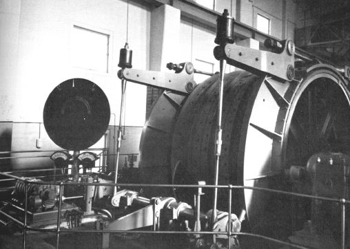
1A winder, a photo from Don Anderson's book "COAL".
It was this winding engine that I assisted on.
An engineer from Vickers came to the pit to supervise the installation.
The first item to arrive at the pit was the main shaft of 1A winder, and it arrived on a low-loader one morning. Fourteen tons in weight and just long enough to go through the access hole in the tower floor, with 9ins of clearance at either end. At one end of the shaft was a toothed wheel, which was part of the self-levelling gear, and if this had been damaged, the whole lot would have had to be sent back.
The shaft was taken to a position at the base of the tower and a lifting beam attached, the crane hook lowered and secured to the beam, and then tail ropes were attached to either end of the shaft to check the swing. The operator slowly lifted the shaft into the air and upwards towards the aperture in the tower floor. It was a very tricky operation to guide the shaft through and there was more than one sigh of relief as he inched it through the gap to complete its journey.
The next job was to get it cleaned off. To protect it on its journey from Vickers, it was covered in paint and then wound round with hessian sacking. The shaft was placed on two wooden pedestals, the sacking removed, and the paint cleaned off with trichloroethylene. We were issued with plastic gloves, and, armed with a box of rags, we set to work. When we stood up after the cleaning session we were drunk from the fumes of the "tricho"and swaying about! The shaft looked really sparkling when we had finished. We left it overnight, never thinking to oil the surface of the two journals and when we came the following morning, the dew had condensed all over it and spotted the journal faces with rust. We had to set to with emery cloth and clean it off.
Martin, the engineer saw the main journal face and he nearly threw a fit. Some idiot at the factory had written "Barrow for the cup" on the face of it, using an electric scriber. He thought at first that the shaft would have to go back to the factory, but he set to work, using scrapers and files to remove it. The same journal ran hot for a number of years afterwards!
To get the shaft running correctly was a really tedious job. The shaft was placed on to the pedestals, bolted into position on the floor. These pedestals had white metal liners, or shells as they were called, to form the bearing surface. When the shaft was in position, engineer's blue was applied to the journal and the caps put on. The shaft was then rotated through 360 degrees by means of a chain, lashed around the middle of the shaft and pulled up by the crane. The caps were removed and the shells checked for high spots. Any found were then scraped off by the engineer and the whole process repeated until the shaft ran completely clean.
The next job was fitting the winding drum to the shaft. The drum was in two sections, which had to be bolted together. After this came the gear wheel with its V-shaped teeth, which in turn was driven by the motor. The holding down bolts for the the pedestals were 3ft long and 3ins in diameter and holes for them had to be drilled through the floor, and, if we hit any steel bars in the re-inforcing, we had to consult with the site engineer before we could cut through them, in case they were part of the main beams.
Whilst all this was going on in the tower, No1 shaft was being furnished with the services, such as pipes and cabling. The excavation of the pit bottom area was carried out from No2 shaft, and at each inset in No1 shaft at both north and south sides, blast barriers made from RSJs and corrugated sheets were erected to avoid any spillage of debris into the shaft.
Continued...